June 13, 2016
\documentclass{article}
% for graph drawing
\usepackage{tikz}
\usetikzlibrary{shapes}
\usetikzlibrary{circuits.ee.IEC}
% for two subfigures in one figure
\usepackage{subcaption}
\begin{document}
\begin{figure}[h]
\centering
\begin{subfigure}[b]{.48\textwidth}
\centering
\begin{tikzpicture}
[
circuit ee IEC,
set resistor graphic=var resistor IEC graphic,
small circuit symbols, semithick,
vertex/.style = {circle, draw=blue!40, fill=blue!10},
]
\coordinate (P4) at (0cm, 0mm);
\coordinate (P1) at (150: 18mm);
\coordinate (P2) at ( 30: 18mm);
\coordinate (P3) at (270: 18mm);
\node [vertex] (V1) at (P1) {1};
\node [vertex] (V2) at (P2) {2};
\node [vertex] (V3) at (P3) {3};
\node [vertex] (V4) at (P4) {4};
\draw (V1) to [resistor={info={$R_{1}$}}] (V4);
\draw (V2) to [resistor={info={$R_{2}$}}] (V4);
\draw (V3) to [resistor={info={$R_{3}$}}] (V4);
\end{tikzpicture}
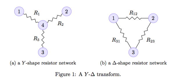
\caption{a $Y$-shape resistor network}
\label{fig:y-shape}
\end{subfigure}
\begin{subfigure}[b]{.48\textwidth}
\centering
\begin{tikzpicture}
[
circuit ee IEC,
set resistor graphic=var resistor IEC graphic,
small circuit symbols, semithick,
vertex/.style = {circle, draw=blue!40, fill=blue!10},
]
\coordinate (P1) at (150: 15mm);
\coordinate (P2) at ( 30: 15mm);
\coordinate (P3) at (270: 15mm);
\node [vertex] (V1) at (P1) {1};
\node [vertex] (V2) at (P2) {2};
\node [vertex] (V3) at (P3) {3};
\draw (V1) to [resistor={info={$R_{12}$}}] (V2);
\draw (V2) to [resistor={info={$R_{23}$}}] (V3);
\draw (V3) to [resistor={info={$R_{31}$}}] (V1);
\end{tikzpicture}
\caption{a $\Delta$-shape resistor network}
\label{fig:delta-shape}
\end{subfigure}
\caption{A $Y$-$\Delta$ transform.}
\end{figure}
\end{document}
Comments Off on Delta-Wye Transform
no comment until now